
Integrity Tests
ISO 1496-4:2019 Series 1 Tests No3 and No4
Container Handling Supplement.
There are two mandatory strength tests in ISO 1496 Part 4 that apply specifically
to freight units bottom corner fittings. Only if these tests are satisfactory can they be issued with a CSC Plate.
Together they guarantee integrity of containment of corner fittings, particularly, the welding,
that secure them to load bearing frames of intermodal freight units.
These are simulation
Lifting and
Constraint tests since it would be prohibitive to conduct live
dynamic tests for all but the most critical of cases, ie military armaments and nuclear material
transport units.
Test No3 Lifting Test
Lifting from bottom corner fittings ISO1496-3:2019

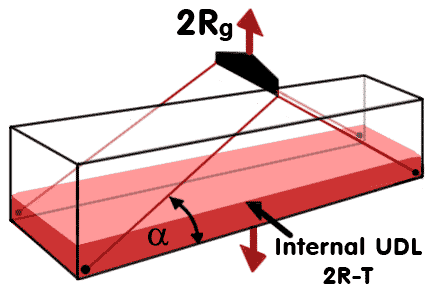
Bottom Corner Lifting Test.
This test simulates the
Static plus Live Loads as covered in
by doubling the MGW capacity. A uniformly distributed internal payload
P having the value of
( 2R - T) is applied over the floor of container to give twice the rating of
2R and is lifted by slings attached to a central beam at the limiting angles shown below in Table 2,
and suspending it to induce a force of
2Rg. This lifting mode also tests the frame strength induced by the resolved horizontal compressive forces that result from accutely angled slings. The unit remains suspended for 5 minutes and when lowered, any permanent deformations of the frame being recorded.
Length
45ft
40ft
30ft
20ft
10ft
Angle α
Table 2 Limiting Lifting Angle α
Test No 4 Restraint Test
When mounted on a transport unit, and in motion, twistlocks transfer forces to the unit when accelerating and braking via the corner fittings, these forces in turn, are reacted by the bottom side rails of the container frame via direct horizontal forces. These horizontal shear forces are influenced by the rigidity of the platform on which the unit is mounted. (Another set of vertical forces are also induced by the inertia force acting at the C of G above the corner fittings resulting with the familiar effect of the forward end tipping down when braking and rearing up during acceleration.
This inertia or body force is product of mass x acceleration acting at the C of G of freight unit hence the need to keep C of G as low as possible.)

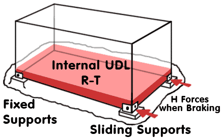
Restraint Simulation Test
Restraint Simulation Test ISO1496-3:2019
This test subjects the container to horizontal corner forces only and neglects both the stiffness of the support platform and inertia effects.
The unit is supported on all four corner fittings alone, a pair being fixed at one end, whilst the opposite end pair are attached to sliding supports. Horizontal forces are applied to these corner fittings, usually via hydraulic cylinders, to simulate dynamic forces induced by acceleration and braking. These forces simulate ± 2g acceleration and are evaluated from the product of MGW x 2 only or
Rx2g. The loading is uniformly distributed having a total value of
R - T. These simulated dynamic forces are replicated by applying half the total horizontal force simultaneously to each corner fitting attached to sliding supports, first pulling and then pushing, inducing tension and compression respectively in the bottom side rail that, in addition, is under bending due to distributed internal loading. The horizontal direct tensile forces (applied in opposite direction to that shown here) are more critical than the compressive forces induced by pushing. Such tensile forces occur when lifting slings are acting in outboard directions, opposite to the more usual vertical and inboard angled arrangements.
Railway Wagon Restraint Test X
A proposed variant of the lug was used to test viability of lashing freight units to railway-wagons. This necessitated a live test of complete assembly shown below.
The lugs were reconfigured to sustain maximum forces when loaded horizontally. The construction of the lug allows for the retaining head to be fixed within the shoe body at any angle. For this application the lug loading range was ± 45° either side of vertical. The retaining head axis was aligned with body axis such that lug could only be inserted when vertical. Once coupled they could not fall free whilst lashing chains were tensioned.

Fully loaded railway wagon ready for testing

Cargo and platform lashing
Rigid chain for base platform and flexible webbing for cargo.

Restrained Corner fitting.
Both vertical and horizontal forces at corner fitting/wagon interface.


 Bottom Corner Lifting Test.
 Restraint Simulation Test


