Container Lifting
Lifting intermodal freight units from bottom corner fittings
Product Developments (Engineering) Ltd
Established 1979


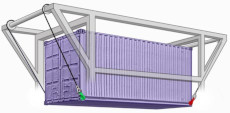
This section deals with problems due to freight loading on lifting lug forces and stability of unit being lifted.
Stability is affected when Centre of Gravity is offset causing freight units to tilt and even swing, also loading increases the lug forces at the "heavy end" thereby reducing the limiting Gross Weight capacity for the lugs. Lifting freight units of any form, is a highly skilled operation and should only be undertaken when all conceivable problems have been antisipated. The HSE publication
could be useful for those in the Port and Docks industry.
The statutary limits of load distributions for intermodal freight units are given in
ISO 3874:1997(E) 3 4.2 Packing Loading and emptying.
for central and offset Centre of Gravity for Uniform and Eccentric loading.
The implications of these are dealt with via links below.
Lifting Cycle
A typical lifting cycle requires a unit to be raised from one place and lowered to another and at some stage the load will be freely suspended and the lifting force will equal the Gross Weight. This is the Static or Dead Load and is the Gross Mass GM or GR (Gross Rating) and equals Payload mass plus Tare.
However, to get the load moving, it must first be accelerated to overcome gravity, this is the dynamic or live load, an inertia force, eventually the load becomes stationary before being lowered. The total lifting force, therefore, is that due to gravity plus the live load, the later being rarely quantifiable and must always be kept to an absolute minimum, consequently the LIFTING FORCE is defined as Rg, the g denoting that it is a force and not mass
Plated containers are certified to withstand lifting forces twice their Maximum Gross Weight (MGW) or Gross Rating (GR) and must satisfy the lifting simulation
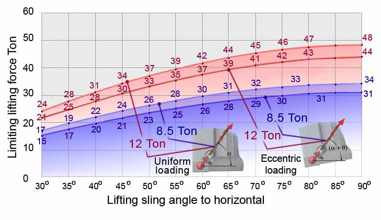
The lug's Working Load Limits are intended to cover the MGW range of Series 1 Containers and are generally 8.5 Ton and 12 Ton giving maximum vertical sling lifting capacities of 34 Ton and 48 Ton respectively for four lugs. When loaded at an angle, within a specific range, their MGW capacity is reduced and charts are given via links above to cover Uniform and Eccentric loading.
All lugs are proof loaded to twice their WLL, this normally covers any excessive overloading resulting from unforseen circumstances during handling without failing. All lifting lugs, therefore, must have a minimum Factor of Safety of 4 for them to be used in the container lifting industry.
This is one of the two ISO Standards that applies to bottom side lifting Lugs,
the other being the offset distance of 38mm between the aperture face and line of action of lug force
as stated in BS ISO 3874 1997 6.4.1.
Basic Lifting Modes
This defines whether freight units remain horizontal
Level Lifting or otherwise during a lift. If it doesn't then it is unconstrained and is normally associated with lifting eccentrically loaded freight units. Various possible effects result when the C of G is aligns itself with top lifting point when using Bottom Lift Sling methods. During alignment the unit will no longer remain level but rotate and swing whilst attaining equilibrium, this is
Unconstrained lifting.
ISO Corner fitting forces induced when lifting
When lifting, the projecting retaining head in the lug body engages within the corner fitting's cavity and sustains the forces necessary when lifting. The four vertical corner forces add up to Rg and the proportion at each corner depends upon payload distribution and, in some cases, kinematic forces due to motion whilst being handled with say, a luffing jib crane.
Corner Fitting Forces

V verical force
H horizontal force
The vertical corner lifting forces are applied by the sling assembly and the resulting force systems for the two loading methods:
Uniform and
Eccentric are both covered in this section. The sling force F is derived from vertical corner force and angle to the horizontal and must not exceed the Working Load Limit of the lug, nor any other component in the sling assembly.
The sling angle has two components α and θ. The principal angle α is determined by sling assembly whilst θ is the tilt angle due to eccentric loading and swing. Swing is transient and virtually imposible to quantify whilst tilt is and found when offset C of G is at maximum limiting 5% of container length and at 50% of container height.
The basic expression giving the lug force F in terms of total sling angle (α+θ)
and vertical corner force is given by equation (1) below.
The Load Factor depends on both Loading and
The sling angles and load factors are covered separately in detail for the two loading cases.
Rg is lifting force due to gravity.
Sling angle α range for ISO containers is given in
F =
Rg x Load Factor
sin(α+θ)
Basic Lug force equation
ISO Corner fitting horizontal forces induced with outboard sling

Outboard tensile forces on bottom side rails
In addition to the vertical corner forces V, the angled inboard acting sling force F induce horizontal H forces that apply compressive forces to the container's bottom side rails. When handling flats these forces could cause the unit to buckle hence the need to use vertical slings to eliminate the H forces.
When acting outboard, these forces induce more problematic tensile forces in the bottom side rails and in the corner fitting welds.
Plated containers should be capable of reacting, providing they comply with
Gross Weights
This is the most significant term associated with lifting and the maximum
GW should not exceed the
MGW stated on the CSC plate whilst the
WLL should not be exceeded in any of the components in the lifting assembly.
Rather than present the limiting lifting sling forces over the angle range in terms of the Gross Mass, an alternative method,used here, would be to give the Gross Weight capacity over the sling angle range working to the WLL capacity of the lugs.
GR is the Gross Rating or total mass
m of freight unit,
Tare
T plus Payload
P
The force/mass/weight units are described in detail at
From
equation(1) the Gross Weight
GW becomes the lifting force
Rg and in terms of total sling angle (α+θ) and the WLL of the lug is
GW =
Gross Weight equation
Uniform and eccentric intermodal freight unit loading
When lifting uniformly loaded freight units all four slings are equally loaded resulting with the maximum
gross weights capacity when lug force is WLL either 8.8 Ton or 12 Ton.
OOG Platforms should only ever be uniformly loaded
Eccentrically loaded containers have an indeterminate C of G position that must be within a mandatory longitudinal limit of 5% of container length and vertically, "as low as possible," (BS ISO 3874 ).
For slings of equal lengths, their forces at the two ends are different, those at the 'heavy end' are used to determine the limiting gross weight (GW) capacity when sling forces are at the WLL of lugs. The effect of vertical position of C of G, are considers at container heights of 25%, 50% and 75% for comparison.
Results for both uniform and eccentric loading are shown via links below
for lugs having WLL of 8.5 Ton and 12 Ton.

Limiting Gross Weights for both Uniform and Eccentric loading
All Gross Weights given here are for the lifting lugs and ancilliary gear that when loaded, apart from the lug, should not make contact with the freight unit sides.
The forces in the lifting gear assembly components, to which the top of chain is connected, may well be in excess of those for the lugs and should be evaluated to be sure it is fit for purpose.


 This section deals with problems due to freight loading on lifting lug forces and stability of unit being lifted.
Stability is affected when Centre of Gravity is offset causing freight units to tilt and even swing, also loading increases the lug forces at the "heavy end" thereby reducing the limiting Gross Weight capacity for the lugs. Lifting freight units of any form, is a highly skilled operation and should only be undertaken when all conceivable problems have been antisipated. The HSE publication


 Balanced Lifting Only when C of G is central
 Sling lengths allow C of G to line up with Rg.
 V verical force
 Outboard tensile forces on bottom side rails
